The unit was suggested to be placed by the manufacturer next to the speedo wire on the dash, which would result in only the speed being corrected, and not the other systems within the truck. Like Mark, I did not do this, and placed the unit directly after the SLABS computer before the speed signal branched off to the other systems such as the ECU and ACE computers.
The SLABS computer was found under the glove box, where the protective cowling had to be removed. The cowl is held on at the front by some clips that wiggle straight out, and at the rear by a screw in clip.

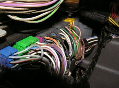
In this area, there are 3 computers bolted together in the one group. The computer that we are concerned with is the SLABS computer which is closest to the outer panel and has 5 plugs connected to it.

The wire that is sent from the SLABS computer is designated the pin code C0504-3 on a KG wire. Thanks to Graeme Small who deciphered this for me means that its the 2nd plug from the back and the wire that comes out is a Pink wire with a green stripe, and it comes from a corner pin in the plug block. In the pictures its the wire that is under my finger, and is the wire that needs to be interrupted by the Speedo correction unit (SCU).

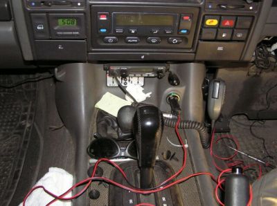
Next I ran a power supply from the fuse block across to the other side of the dash, where the SCU would be mounted next to the SLABS computer. When I mout this thing properly it'll probably end up under the dash on the drivers side where I can switch it easily and mount it where there is plenty of room. Not tonight though.
The electrical wire was then run through the welding wire

and pulled through to the other side to provide current for the SCU.

The SCU needs to have a power supply that is active when the ignition is active, and also when the starter motor is being used. Finding switched power is ok, but I'm not sure if power during start up is as common. Anyway, I found an outlet that was suitable in the fuse block that was not being used. My truck is a TD5 Auto with ACE, and so I don't know what this particular outlet is for...... but its good for the SCU.

The power supply wire then had a female spade terminal fitted and connected to the power outlet.

Back to the SLABS loom, the C0504-3 Pink wire with green stripe was relocated.


The wires were then cut and fitted with electrical connectors. The connectors cover the female end completely to prevent short circuits. The female connector goes to the SLABS output on this wire, which is the plug end of the KG wire.


On the SCU, the red power input lead is connected to the power lead run from the fuse box, the Earth wire is connected to the body as a return lead. The Signal input is connected to the SLABS computer via the installed female plug on the KG wire next to the plug and the SCU output signal returns back to the installed male plug on the KG wire.
Larger pics are at:
http://www.slunnie.com/coppermine/thumb ... p?album=28