I havent built one for a while, so here we go.
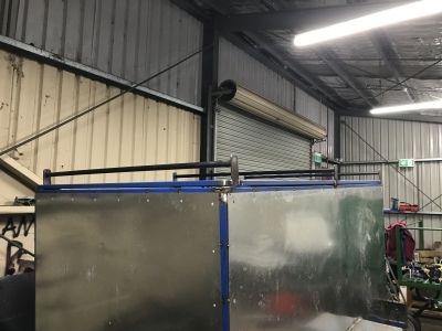
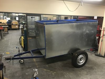
This is the old banger, it is an enclosed karting trailer and built as lightly as possible for a fairly lightweight load, but it is such an amazingly useful and handy trailer. An oldie but a goodie!

These days however the enclosed trailer gets used for heavier duty work such as lugging fencing gear, engines and gearboxes, firewood etc. I want to design and make a replacement trailer so that it can be that elusive trailer that can do everything, well as best as possible.
The trailer needs to have heavier load rating, it needs to have a stronger floor, it needs to be able to tie down loads in the load space, it needs to be able to better accept loading by engine crane with roof clearance, it needs to be able to receive loads from ANL , I would like it to not leak water (not that the old one does) and I would like the 2 side swing doors to be better designed for usability.
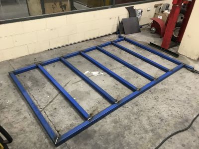
So, here it starts. The chassis is 50x50x4 RHS. I always run heavy wall main chassis rails to ensure suspension points are secure and don't require plating, they are the keystone to a good trailer and I hate it when trailers skimp in this area. The trailer spec is 1500kg, and I would almost always run a 75x50 chassis for that load rating, but this trailer is pretty short it will be well supported by the drawbar and suspension points. The cross members are spaced at 400's, so the trailer is 2 sheets long at about 2470mm iirc long and so the floor is well supported. The chassis has been cut, assembled, squared, tacked, checked, top and bottom welds.
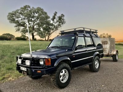
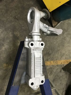
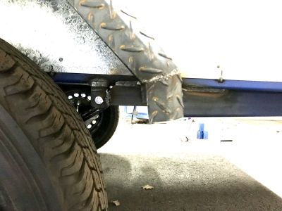
Chassis is fully welded with fillets. Suspension points are added and welded in. These are 1500kg slipper springs, simple and effective. The axle is a 45mm square, when running 4WD tyres as I rule of thumb I go straight to 45mm irrespective of load rating for strength. Brakes are over-ride, cable operated disc brakes. Slimline bearings and Landcruiser 6 stud hubs running hilux wheels. The axle length was specified for these hilux splitties with 50mm tyre clearance to chassis on each side, but it looks like there may be more than that (did I add 50mm/side and the supplier do the same???). I've got some 17" Hilux steelies that may bring the clearances in a bit, will check it out a little later. The axle is in a SOA arrangement rather than a conventional setup, this is to bring the trailer ride height up higher. The normal tow vehicle is my Disco2 which sits about 6-7" higher than standard, so having the trailer axle setup like this actually levels it out. Drawbar has been added, this is made from 75x50x4 with a clearance to the body of 1350mm. The coupling plate is on but obscured. I've done this a little differently also, rather than overhanging the plate so the front bolts are off the end of the drawbar, this time I have shifted the coupling plate a little further rearward and I will drill out the top of the drawbar so the couplings front bolts go through the coupling plate and through the top of the drawbar. It looks a bit tidier, see how it goes... I'm sure I'll find out why we don't normally do it that way shortly. Trailer is ready to flip onto its wheels, my Yr12 are really handy for this!
Oh, just looking at the welder, we run a fleet of these WIA 270C Mig welders. I cant speak more highly of them. The cabinets are really intelligently designed, they know what fails and why and have designed for it. eg, drop down lids. These are transformer rather than inverter, so they are heavy but should also have longevity. The welder is very forgiving and great for people learning to weld while at the same time they have a lot of grunt, the settings can be off a little bit and a good weld can still be put down. The students have about 3 base settings and almost all work is done on those settings. We run 0.8mm wire for flexability between thin 1.6mm welding and chassis etc up to about 5-6mm and the odd bit of 10-12mm plate. We run about 10-15l/min gas flow rate with Argoshield light. With a 270A gun we melt very few contact tips these days. I'd recommend these, they do run on 15amp but for heavier work over 6mm need 20amp single phase.

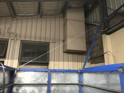
You can see below how the spring over axle arrangement levels the trailer behind my Disco2.
Just out of interest, this is my planning sheet. I could glorify it by calling it a workshop drawing, but that would be unfair to legit workshop drawings. It's how I calculated parts, parts into metal lengths, joints etc and consolidate the trailer design. It meant that I could spend an hour on the cold cutting saw and have all of the metal for the project cut, cut exactly to size and be ready to go. Calculating and pre-cutting makes the building process so much more efficient than otherwise and it eliminates any gaps. Every part in the trailer is marked with a part number and the drawing shows its location in the project.

The trailer is flipped onto it's wheels now, thanks boys! You can see how the coupling plate has gone on with a bit more clarity now. The coupling plate is welded underneath but not on top at the moment, I'll weld the top later.
While sitting on top of the chassis I have welded up the frame that forms the top of the enclosed box and also a second matching frame to form the flip top lid. I've formed these up on top of the chassis to make sure they are a perfect match and that nothing goes out of square when the box is made up. The chassis is square to within 1mm of the diagonals, but if there is any error then this method duplicates it into the other parts so that everything stays consistent. Even though these 2 parts are not needed right now, they needed to be made now before the carcass construction starts.

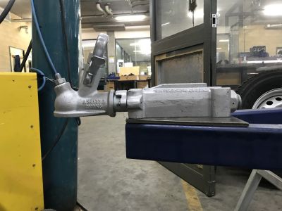
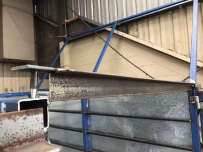
About the coupling, I've taken a couple of pics of how it will look installed (brake plate isn't in place for the photos), but there should be loads of space for the towbar to not connect with the brawbar.
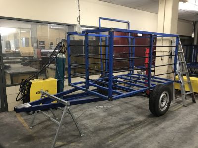
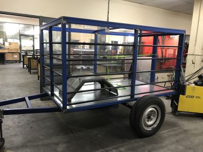
The carcass has been constructed here, uprights gone in and tacked into place and the top of the box put on. Well that was an interesting experience. I construct using a builders/carpenters square and then check by measuring the diagonals. So it turns out the builders square is not actually square. Even the kids were looking at it wondering wtf. Fortunately because everything was squared up the same way, when the top went on it pulled everything back to square again. Square has gone in the bin, I'll show more sympathy from now on, 6 replacements are on their way. The carcass is just tacked up and the rear/top member will remain only tacked so it can be removed a little later on. I ummed and ahhhed about whether to run the centre upright at the front, and have decided to run this to increase strength if there is a car crash - just make it a bit stronger like a headboard from a ute tray or tabletop trailer. Pleased that ordeal is over!

The carcass has been fully welded in now, there was a bit of movement from weld contraction but it all seemed to correct itself fortunately... well, I think...
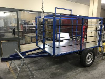
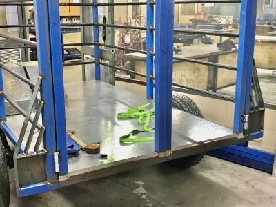
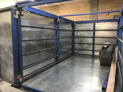
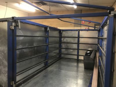
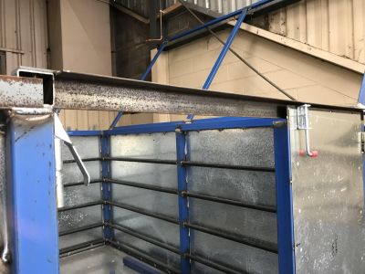
The interior is lined with rope rails so that everything can be supported and tied down into place. I think that they will also be really good to mount a shelf if I ever need to. These are just 20NBx2.6 but will be pretty strong I'd say! They're spaced at 230mm and tacked into place. I've got an even spacing using timber spacers (see bottom corner, they're still in place), starting at the top rail and then working down, shortening the spacer as I went. I'm thinking that after the floor goes in that I might add another unplanned rail between the floor and the lowest existing rail for a lower mount and to catch everything that slides around in the bottom of the trailer before it smashes the sides out.
The rope rails were only tacked in but have now been welded. The floor has also been cut in. That was an interesting exercise as it couldn't be test fitted, it was just measure, mark, cut and hope for the best... What made it difficult to get the floor in was that it was cut around the uprights which already makes it difficult to get into place, but the rope rails wouldn't allow it to just drop into place. Some 75x50 and 50x50 over the top placed under the middle of the sheet to bend the sheet down to flex it into position and it eventually found it's place in the trailer. I can assure you that front floor panel will never be taken off the job, and if somebody does get it out, then they deserve to keep it! The floor is just sitting there at the moment, it still needs welding. The floor is 2mm Gal.
I've changed the hilux splitties out for 17" hilux steelies. The offset is quite a bit different between the two rims, with the 17's sitting a fair bit further inboard. I don't think the clearances are enough between the tyre and the chassis so will be putting the splitties back on. I do want to run the 17's on the trailer and to save the set of splitties for a future project, I'll have a think about which way I want to approach this though. Safety chain is on, coupling is in place but not bolted down yet, I'll do that after I get the jockey wheel.. hopefully tomorrow! The flip lid, I've added a cross-member into the middle of it to support where the sheets will go, hinges have been welded on (3x). The hinges are HD gate hinges which come in left and right orientations, they've been stripped and combined so they're all the same and fold in a way that allows the top to fold all the way down. They have been welded in so that the top is not removable, hopefully that will save any accidents, injured people and a damaged trailer. In the rear corners I have also cut out the beginnings of light boxes, just 2mm hot rolled that has been cut to width and a 25mm fold in the top. It will get boxed up a bit more a little later and used to brace the wall from flexing around.

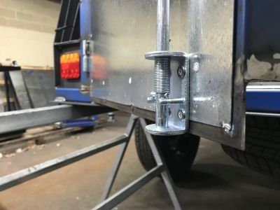
Borrowed a jockey wheel from our components supplier until stock arrives, and installed it. Welded the top of the coupling plate to the draw bar and installed the coupling, splitties swapped back on again.
Framed up the rear doors. To do this I installed the hinges onto the carcass, they are set so the door isn't removable. Measured and cut 50x50x2 RHS door uprights and 50x50x3 EA for the top and bottom rails. Measure with the hinges in place and setup with an 8mm spacer underneath between the door and the trailer floor and an 8mm gap between the doors so they can swing open. The gap between the doors and the carcass is whatever the hinges generated. The top gap is about 10mm. Trailer bodies are quite flexible and these gaps will allow it to move around without rubbing, wearing and bending everything, its not good to have tight fits. Everything was spaced and clamped into place, tacked and then the doors removed and fully welded before the external welds were ground flat so a skin could be sheeted on to it. Once the door frames were finished, they were reinstalled and checked, fortunately they stayed square and didn't twist. The hinges were then tacked in place and these are now ready to be fully welded before the rear door skins go on.
The drawbar crossmember to mount the spare tyre is now in. The tyre is just sitting there though. Behind the trailer the sheet has all been cut so that it can be skinned when it is up to that stage. The skin is all 0.95mm Gal.
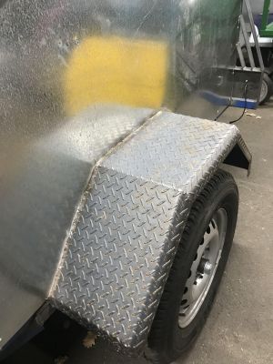
The guards are 2.1mm checker plate. I scabbed around and found enough to make a set of guards. These were cut to length and then were cut to width. They are a L & R set. The outer edges were folded at 45 degrees at 1" from the edge and then 2" from the edge. Then they were measured for overall guard width, cut on the guillotine and a 90 degree bend in the panbrake with a 1" fold on the body side. That forms the section profile of the guard. Then where the bends are needed I used an angle grinder with cutting disc to cut the folded sides and tapped the sides to misalign for folding the guards into an arch. Into the panbrake and set to 45 degrees (+ springback of about 15 degrees for this which was abnormally high!) and the guards were shaped. Trimed where the sides overlapped, tacked and welded. Boom, matching checker guards which will hopefully be a bit more interesting and wont bend when I walk over them!


Boxed up the light boxes with some 50x5 flat MS. I thought it might be cool to make a brace for the sides also to help stop them from flexing around a bit, so continued the outside of the frame for the light box up on an angle to meet the trailer enclosure. Then I thought a couple more might look cool as well. Extra bracing, aerodynamic for a box and a bit Mad Max in its styling. Hopefully they don't reject it at rego... I guess I'll sheet it and add LED lights if they do. Something different.
Added an additional rope rail, this one just skirts around the bottom. this will give just a low tie point and help stop stuff smashing into the sides. All of the rails are now fully welded in. The floor has now been welded in, just around the outsides, but not underneath yet - I wasn't ready to get burnt today!
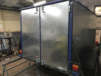
I started to sheet the thing... I had been wondering if the walls being 1mm thick was too thick. After hitting it with the welder, I'm now wondering if the walls are too thin!! They wont take much heat when welding, thats for sure and they move around a lot when welding also. It's obviously been a while since I've sheeted a trailer. I've sheeted the front and both rear doors. They still need more work, but its a start. The sides will be a nightmare I suspect. Its about now that I'm regreting doing the rear light cluster all Mad Max. I'll pay for that one later!
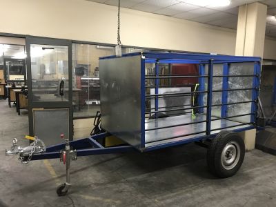
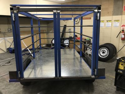
I finally got around to cutting the sides in. It was a pretty straight forward process cutting the sides around the rear light housing, and it came out reasonably well. I'm sure it could have stuffed up very easily but luck was on my side. Both sides are on and hanging with tack welding across the tops of both sheets, but they still require welding all round. Now it has a skin around it, it's sort of mysterious as to what is on the inside... maybe its a couple of girls jelly wrestling, maybe its secret drinking bar, perhaps a portal to another universe, could it be full of bullion, but more likely its just a pair of checker plate mud guards that are waiting to get welded on..
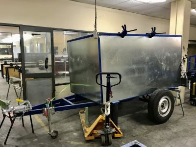
The axle has been swapped out for one that is 75mm longer to accomodate the Hilux 17" rims which have a different offset compared to the Hilux 16" splittie that were on it. It's still a 1500kg 45mm cable disk brake setup. The sheet was tacked in place and then tacked all around the outside. To try to prevent movement, the sheet was also tacked on the inside. The sheet is held on with tacking as it wont take the temperature of stitch welding without blowing apart. It's not a great way of doing things, but I'm hoping that if my 20year old trailer which is done like this is able to stay together, then hopefully this one will also. The floor is stitch welded in, this was done with a standard 25mm/200mm.
Just how the interior turned out, the lid has been flipped up a bit in the RHS pic. I'm thinking after the trailer has the finished applied that the lid will have an opaque polycarbonate cover put on it to allow light into the box. The flip lid is held down with a few overcentre latches
This trailer gets external sprung sliding bolts to lock the doors. I'm doing it this way so that the locks are accesible and the doors are better supported when there is load against them. The lower cross member has a flange welded onto it that the sliding bolts will go through - I will round off the corners later. Top cross-member will be replaced with a totally new redesigned part, the current one is in place just to support the carcass during construction.

The top rear Xmember is removable. The original carcass Xmember there was removed and replaced. This is just made from 50x5 flat and 50x50x3 EA. The ends are made from 12mm round with the ends machined into a taper to make fitment easy. The design allows a few things:
1. It is removable to make loading possible using hoists.
2. Prevents water coming in through the top of the doors.
3. It allows upper door sliding bolts to lock into it.
4. Locks into place when the lid is closed.
I was going to insert a crush tube into the trailer frame for the Xmember to locate in, but it will drain into the corner post and so it wont work. The Xmember now will just locate into a hole, and I will just use a 50x50 plastic plug to seal the top which will allow access if anything falls in the hole.and drainage if needed. The holes for the bottom sliding bolts are drilled and the locks are operational. The tops ones... well, I broke the new drill bit in the bottom holes - very annoying!
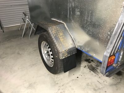
Guards are now on also. Levelled the trailer with a digital spirit level and then levelled the guards. Done using centres from the axle line. The guards sit 150mm over the tyres which is a fraction more than the chassis clearance of the fishplates (it is sprung over, so the fishplates are on top of the springs). Hopefully the tyres don't hit the guards! I managed to catch fire welding the guards on, I haven't done that for a while! I just caught a spark in the cuff and it lit up. No burns due to an old shirt underneath.


Top rear Xmember drilled out for the upper locks. Its actually a pretty cool setup how the doors lock in top and bottom. That top cross member is as solid as a rock when the lid is locked down, no movement at all. Hmmm, I'd better put the other bolts in those latches.

The flip lid has had a cable put on it. Just some chain link welded top and bottom, 3mm plastic coated cable (so it is quiet and not abrasive) and a couple of D shackles. Its also really good because to close the lid you can just grab the cable and it pulls the lid across. Its close with the front latch on the lid, but it all works well.

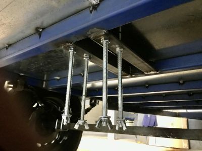
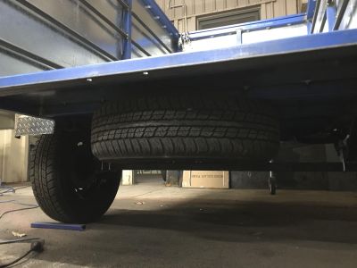
Spare tyre has been mounted underneath. It is mounted using 50x50x6 EA and 1/2" threaded rod. Because I made an error and placed the axle 1"/ft rear of centreline instead of 1/2"/ft rear of C/L the spare is in a good spot behind the axle to take some weight of the nose. It sits just behind the axle, so I don't think it will promote trailer wagging. I think that location will also settle the trailer down over bumps when empty. That said, it is really really hard to get the spare tyre onto the bolts. It may be better with a lighter tyre like the normal Ford pattern etc, but with the steel 4WD tyre it was a massive PITA and very heavy! It needs a winch. That said, it is in a good spot. Valve faces down so pressures can be checked. If it falls out, It'll probably take me a year to notice.

Tied the leading suspension points into the drawbar with 50x5 flat to increase rigidity. I build with heavy wall in the lower chassis rails and drawbar so there isn't cracking issues ever, even at the expense of weight, however these additional plates on the inside and outside of the chassis between the suspension mount and the drawbar are there to provide additional reinforcement by removing any flex which may lead to a failure. The way we do this normally has never resulted in a failure that I'm aware of, but this will make sure. On the inside there is a cutout in the DS plate to allow the wiring harness to pass through. Those new plates also gave the guards a bit more weld area for increased rigidity.
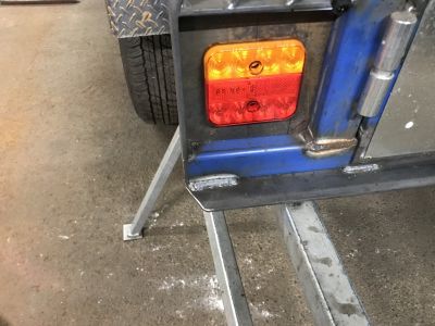
Tail lights have gone in. I'm using a plug and play system because it is easy. The students gave me crap about having blinkers at the top and not the outer sides, its just like that to make sure that the blinkers can be viewed from the necessary side angles, but I think even if they were mounted the way the students like it would have been absolutely fine.
The top and bottom plates that the doors lock in to have been trimmed back and rounded off a touch. I've done this as a bevel rather than rounding just so it fits in with the trailers square design aesthetics. Just dresses it a bit better than what it was and hopefully no injuries come from it.
The missing bolts have gone into the door sliding bolts. This one was an interesting one as a nut wouldn't fit behind the door because it closes onto the floors rear Xmember. In the end I drilled it out 5mm and tapped an M6x1 thread and used the door as a nut instead. Then just trimmed the excess bolt thread off. I might loctite those bolts after it gets painted so they don't eventually fall out.
Sheet welding... I'm always banging on to stitch weld sheet otherwise everything will bend and buckle...righto teach, just stitch it. So I look at my guards which are welded to the chassis and through the sheet walls to the carcass so that they are rigid. Then I stitch the sheet walls to the guards and think to myself that the welding looks pretty cool and the sheet hasn't moved too much. So in the spirit of looking cool I MIG seamweld the entire guard to the sheet and buckle it like a champion. <forehead slap> Oh well, done now and at least water shoudn't get through it.
A couple of SCA mud flappys to make it legal.
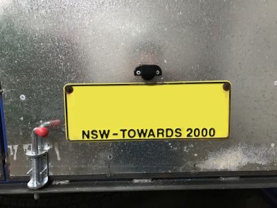
Drill out the number plate holes, position and fit the number plate light. I trialled external wiring, but ended up going internal as it was so much neater.

Built some roofracks. 3x Tradie racks. Just 50x5 ends with 20NB rails and spaced 50mm up for a low profile. Nothing to heavy duty.... or heavy due to the flip lid.